http://www.rcgroups.com/forums/showthread.php?t=2316420
Programming the Sunrise 20A Slim ESC (Atmel Version) Revision long-20_V1.1
The Sunrise Slim 20A ESC is becoming very popular among the 250 FPV Quad crowd; its unique footprint, 20A capacity and 5.5gram bare weight is a promising package. Add 500Hz speed and Active Braking (and now, even experimental 1-Shot/125) to the legendary BLHeli mix of adjustments and you have quite an impressive little ESC for $8-11.
| This image has been resized. Click this bar to view the full image. The original image is sized 768x1024 and weights 113KB. |
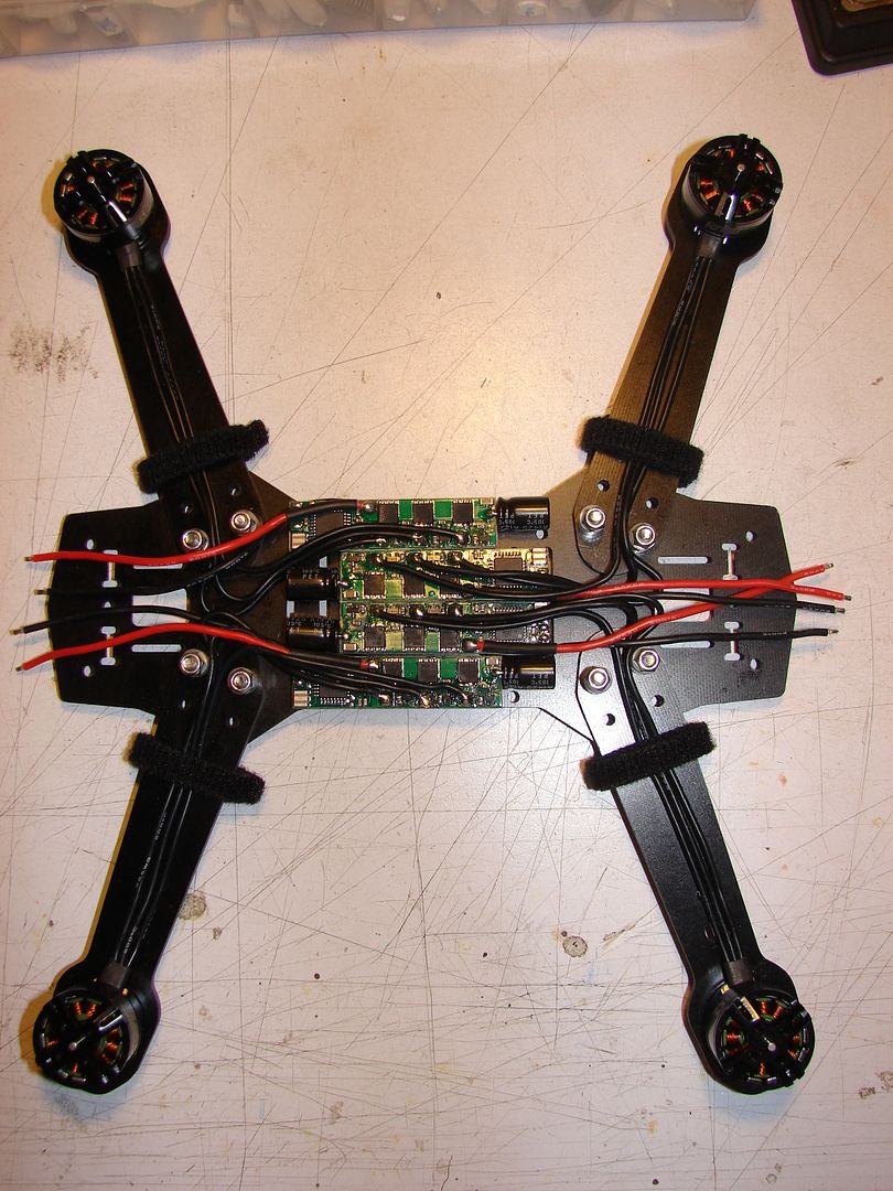
On the ZMR250/H250 generic FPV quad, that unique footprint allows one to set up the ESCs between the lower frame plates like so for a super-tidy build; just as if the ESCs were MADE for it...
| This image has been resized. Click this bar to view the full image. The original image is sized 768x1024 and weights 106KB. |
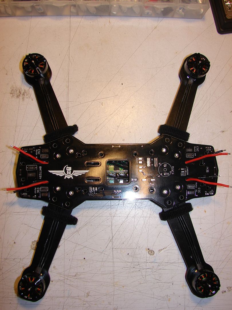
...and if you're using a full-plate PDB like the OverCraft PDB shown here, the wires exit EXACTLY where you want them to.
Recently; Sunrise released a new version of the Atmel-based 20A Slim; long-20_V1.1 . This How-To focuses on this version, as I found myself forced to reverse-engineer mine a little to make it work.
Here is the BLHeli "Supported Atmel ESCs" page for the Sunrise Slim 20A:
| This image has been resized. Click this bar to view the full image. The original image is sized 728x532 and weights 198KB. |
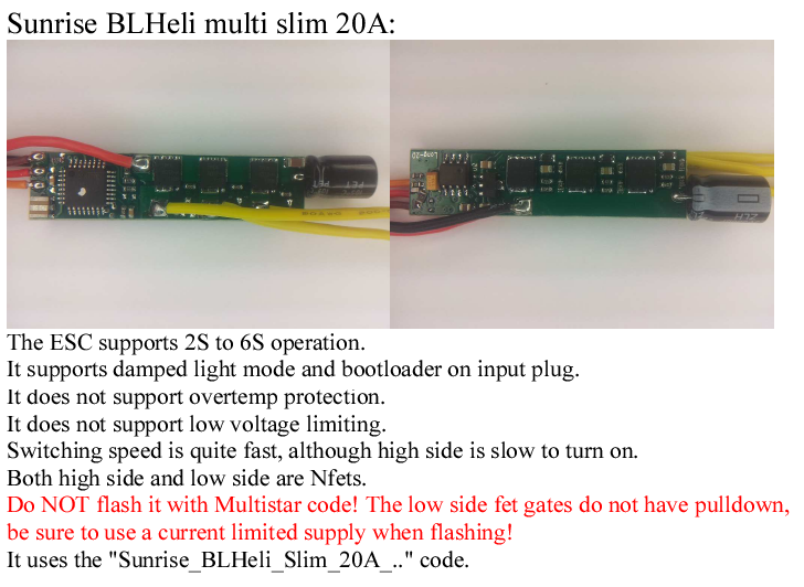
The photos show an original revision Sunrise 20A Slim; it normally has an inverter transistor in the input which is commonly modded out with some resistors as seen for 1-wire Programming. Aside from this difference the ESC is the same, and the same safety concerns regarding "No Pulldown" and "Current-limited Power Supply" still apply. I have personally smoked an ESC due to this issue; it is NOT just folks being over-careful.
I cannot emphasize enough the importance of using a Current-Limiting power source whenever programming and bench-testing your ESC.
Every time you use 1-Wire Serial to flash ANY ESC without a current-limited power supply you're taking a gamble that a random pulse from the programming process is going to cause a High-Side FET to turn on at the same time as a Low-Side FET, creating a short circuit. If you accidentally flash the wrong firmware, it can do the SAME THING. This applies to ALL ESCs, but this model is MORE prone to it than others due to its design, hence the RED TEXT warning in the BLHeli instructions for this ESC.
Please, PLEASE, for the sake of FETs everywhere, build and use the "3057 Current Limiter" and use it EVERY TIME you test your ESC after PROGRAMMING or SOLDERING on it for any reason.
| This image has been resized. Click this bar to view the full image. The original image is sized 1024x739 and weights 125KB. |
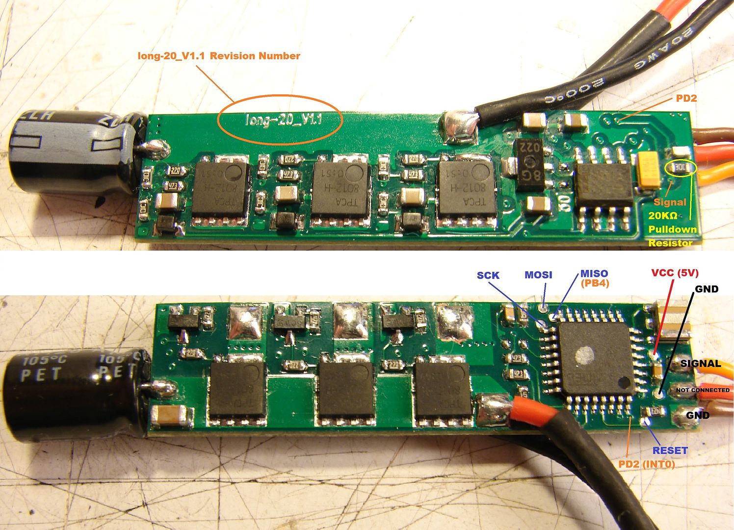
Here you can see a closeup of one of these new ESCs; I've highlighted the usual solder locations if you want to flash the ESC the old-fashioned way by soldering wires connected to a USBasp. Note the difference in the Signal input and the 20KΩ pulldown resistor.
It appears that this model ESC is showing up in the wild flashed with multiple firmware versions; most support 1-Wire Programming out of the box, some don't. If yours doesn't, you'll have to flash it first with a USBasp to put a generic BLHeli Firmware on it that supports 1-Wire Programming.
While I didn't originally mean to, this tutorial has evolved into a pretty thorough walk-through that is applicable to programming almost any ESC with BLHeliSuite; many ESCs will need the 1-wire bootloader installed first, so I'm going to keep things in the usual order so everything remains linear.
If you don't know whether your ESC supports 1-Wire Programming out of the box, or if you know yours DOES, you can skip ahead to BUILDING A 3057 AUTOMOTIVE LIGHT BULB-BASED CURRENT-LIMITER, continue to PART 2, MAKING AND USING THE 1-WIRE SERIAL INTERFACE and try connecting to it via the Servo wire.
If it doesn't work, jump back to BUILDING A PULL-UP CIRCUIT ADAPTER FROM A SALVAGED SERVO CABLE before you try flashing with the USBasp. You MAY very well NOT have to cut the wrap off your ESC.
PROGRAMMING YOUR ESC WITH A USBasp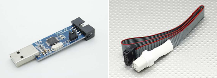
http://hobbyking.com/hobbyking/store...trSearch=atmel
The simplest way to do this is to use a USBasp and an Atmel Programming Socket like this one. It's available from HobbyKing for $20.
If you use it to program 4 ESCs, it will pay for itself in saved hassle and potentially smoked ESCs. Really, it's a no-brainer.
| This image has been resized. Click this bar to view the full image. The original image is sized 1024x820 and weights 76KB. |
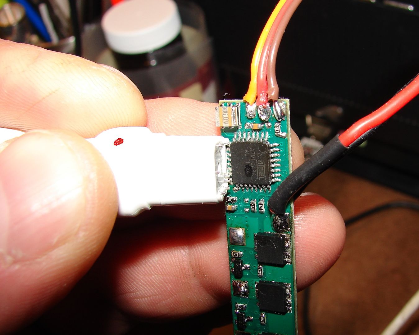
Just plug the USBasp into your PC, plug the Atmel Programming Socket into the USBasp, then align the corner of the socket with a Red Dot on it with the dot on the corner of the Atmel CPU.
| This image has been resized. Click this bar to view the full image. The original image is sized 1024x797 and weights 74KB. |
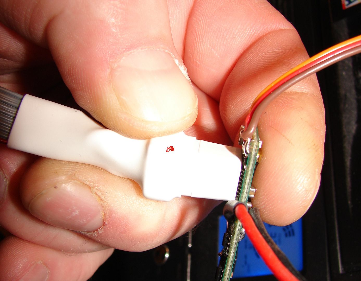
Press the socket down over the CPU with your fingers and hold, then flash the ESC. Takes mere seconds and it's done.
If you need to be able to program with a USBasp and you don't have access to the Atmel Programming Socket, I've identified the solder pads required for programming on the closeup photo of this ESC at the top of my DIY.
| This image has been resized. Click this bar to view the full image. The original image is sized 1007x763 and weights 133KB. |

For reference, here are the standard Pinouts used by most popular USBasp/ISP programmers.
Remember, we don't need to provide power to the whole ESC when flashing via USBasp, so the Current-Limiter is not necessary here. We ONLY need it for 1-Wire Serial programming and whenever we first power up the ESC after programming or soldering on it.
First, go to the BLHeliSuite Thread on RCG: http://www.rcgroups.com/forums/showthread.php?t=2136895
The first page always links to the latest stable version of BLHelisuite.
Download BLHeliSuite, unzip the package to a directory on your desktop, and while you're reading the BLHeli Manual and the other documents in that folder, play around with BLHeliSuite so you get familiar with it. Also, I recommend reading at least the first and last 5 pages at least of the BLHeliSuite thread; prefereably first and last 10 pages to have a feeling for what's being done with it.
I REALLY don't have time to do a tutorial on EVERYTHING involved in how to use BLHeliSuite as part of this DIY; I'm going to assume that you've flashed an ESC before and hve at least taken the time to make sure you are reasonably familiar with the BLHeliSuite dashboard.
I am also going to assume that if you are using a USBasp, you know how to install the drivers for it and you know yours works.
So here we go, flashing with a USBasp:
| This image has been resized. Click this bar to view the full image. The original image is sized 822x696 and weights 209KB. |
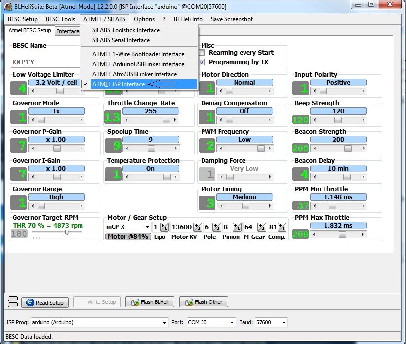
Plug your USBasp into a USB port; then launch BLHeliSuite and from the [ATMEL/SILABS] Tab, select [Atmel ISP Programming Interface] . The Dashboard will switch to the [Atmel BESC Setup] Tab and populate with a generic configuration template.
| This image has been resized. Click this bar to view the full image. The original image is sized 821x698 and weights 227KB. |
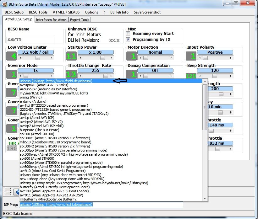
In the dialog at the bottom, select your USBasp or ISP Programmer. As you can see, BLHeliSuite support oodles of common Arduino-based programmers; I have a USBasp clone with USBasp Drivers, so I'll use this one.
| This image has been resized. Click this bar to view the full image. The original image is sized 820x697 and weights 217KB. |
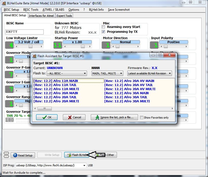
Select [Flash BLHeli] just above the interface selection dialog. A file dialog box will pop up.
| This image has been resized. Click this bar to view the full image. The original image is sized 820x699 and weights 230KB. |
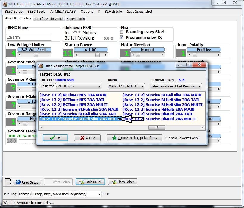
Scroll to the right until you can select [Sunrise BLHeli slim 20A MULTI] for the MultiRotor Firmware build.
| This image has been resized. Click this bar to view the full image. The original image is sized 820x698 and weights 180KB. |
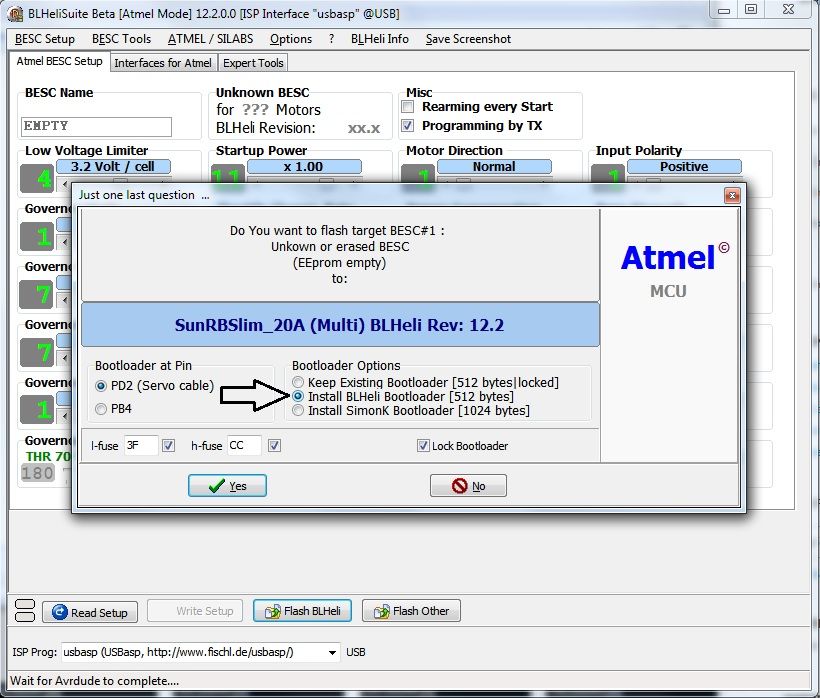
Select [Flash BLHeli Bootloader] ; leave everything else set at the defaults unless you know what they do and want to change them. I don't think you'd be here if you did, though.
Click [YES] to launch AVRDude and start the flash process. The following screens will flash by automatically and pretty quickly unless you have a bad connection; then it'll pop up a warning about being unable to read to or from Target Device. If this happens, realign your programming socket to make sure the pins contact the proper legs of the Atmel chip and try again.
| This image has been resized. Click this bar to view the full image. The original image is sized 820x700 and weights 196KB. |
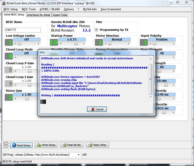
Erasing the chip and loading the Firmware file into memory; then writing the Firmware to the chip...
| This image has been resized. Click this bar to view the full image. The original image is sized 821x700 and weights 212KB. |
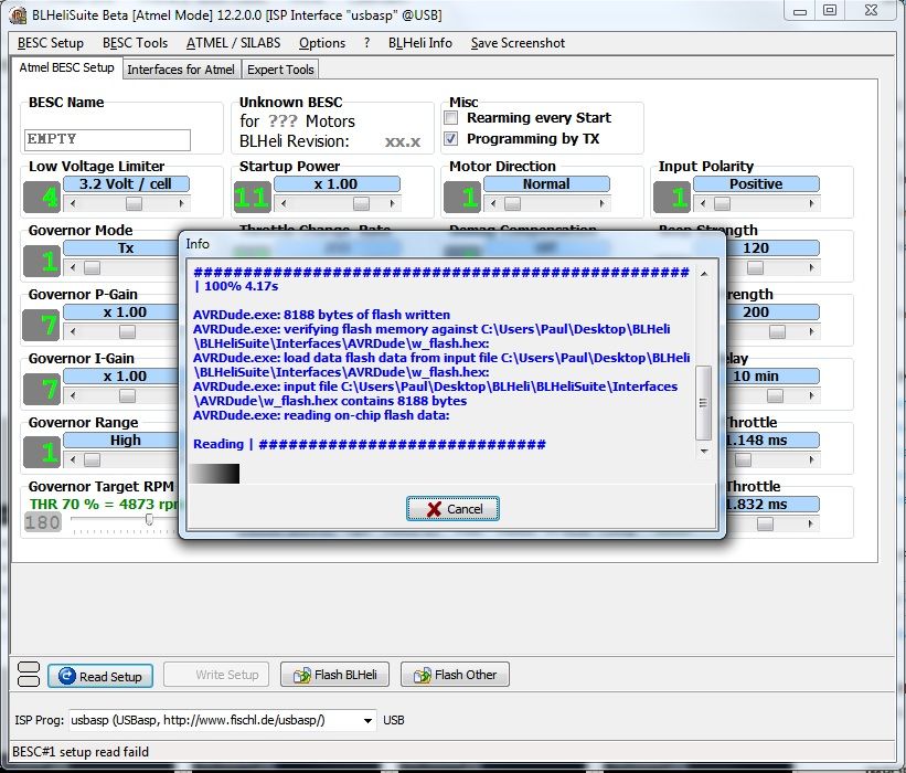
Reading the flash back to compare to the Firmware file...
| This image has been resized. Click this bar to view the full image. The original image is sized 817x697 and weights 186KB. |
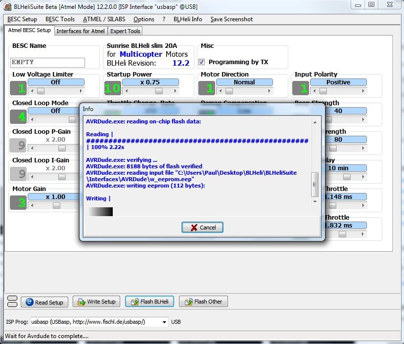
Verifying the Firmware and writing EEPROM Data (Settings)...
| This image has been resized. Click this bar to view the full image. The original image is sized 818x698 and weights 190KB. |
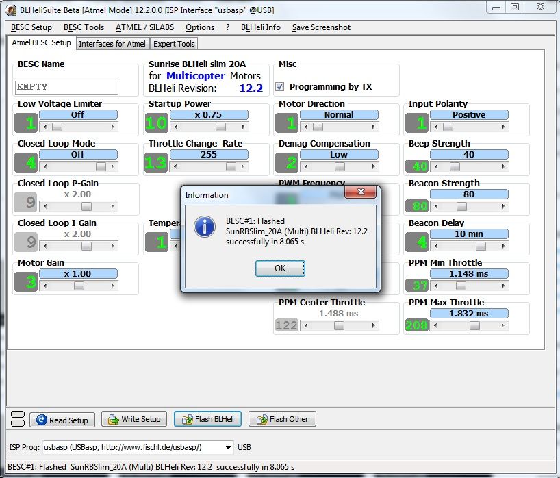
And... SUCCCESS!!!
Now, you can reprogram the ESC anytime you like over the Servo Wire; but unlike with the USBasp, you have to power up the ESC to do this. For safety's sake and to prevent smoking your ESC due to random FET misbehavior, we need to use a current-limiting power supply.
There ARE bench supplies designed to do this but only Total Geekoids like myself usually have them; and even mine doesn't shut down at what I'd consider a low enough current. So after talking with a few folks over on the BLHeliSuite thread, I hit upon a solution that is good for both programming ESCs, and for testing them without letting the magic smoke out.
BUILDING A 3057 AUTOMOTIVE LIGHT BULB-BASED CURRENT-LIMITER
| This image has been resized. Click this bar to view the full image. The original image is sized 1024x490 and weights 62KB. |
The more I speak with the folks who know what they're doing when it comes to flashing ESCs, the more I am shown that there is a chance of ANY ESC blowing one or more FETs during 1-Wire programming if you don't use some form of current-limiting on your power supply; and some (like this model) are more likely than others to do so.
You REALLY should ALSO use one for initial bench testing after soldering up your ESCs; how many stories have you heard of ESCs going "POOF!" when first powered up due to a poor soldering job or errant strand of wire?
This device will turn that short into just another low-current load; saving the ESC so you can fix the soldering mistake, not just replace the ESC after you let the magic smoke out.
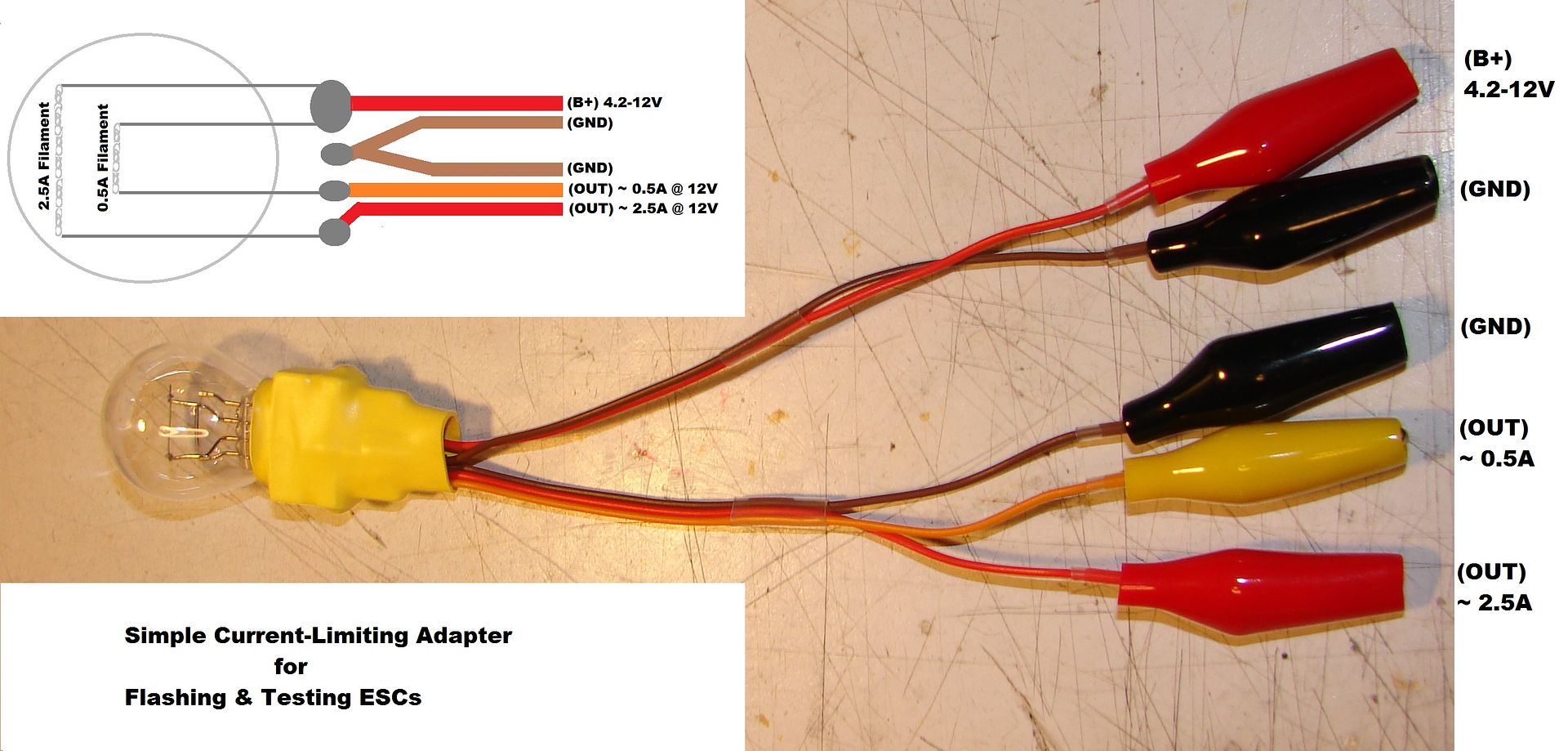
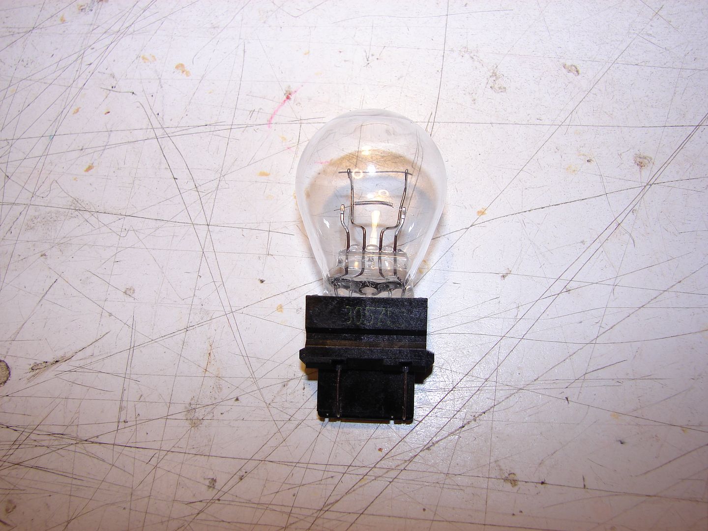
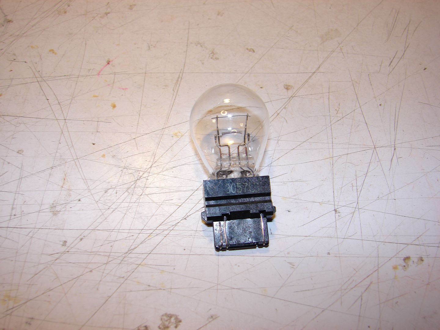
We're going to build this. It's a two-stage current limiting resistor that uses a 3057 12V automotive taillight bulb as the resistive element. The light bulb as ballast resistor idea is one that's been around the electrical/electronics hobbyist community for a century... really!
While I was researching my issues with this ESC, robca over in the BLHeli thread mentioned the wattages/current limits he used for most of his work.
| This image has been resized. Click this bar to view the full image. The original image is sized 1024x768 and weights 93KB. |
Based on those figures I extrapolated that a 3057 taillight bulb should work well as a two-level ballast; one with very low current (approx 0.5A) for providing power during programming, and another higher-current ballast (approx 2.5A) suitable for no-load testing of smaller ESC/motor combinations as a "reality check" type test just to prevent smoking a new ESC when you're first trying it out on the bench.
(FYI, a 4057, 3157,3357, 1157 bulb will also work; the 3057 is just what I had handy. This isn't rocket surgery; the tolerances are pretty broad.)
Remember that you'll want to use the ballast ANY TIME you're planning to reprogram your ESCs using the 1-wire Serial interface, even after you have the whole quad assembled. Just hook it up inline between your battery and the main power on your quad. (This is not necessary when using a USBasp, obviously, because the USBasp provides 5V power to the CPU without energizing the FETs.)
I recommend removing your props first, any time you program ANYTHING on your quad.
The BLHeli Manual recommends using a current-limited power source on these ESCs due to lack of a pull-down circuit; this can cause a FET to "latch-up" and result in an effective short-circuit if any random pulses hit the FETs during the programming process. The programming process can cause a High-Side FET and a Low-side FET to turn on at the same time; this ALSO results in a destructive short-circuit. Accidentally flashing the wrong firmware can also do the same thing.
I suspect that NOT using a ballast may have caused the initial damage, or caused a FET to latch-up, in one of my ESCs which subsequently smoked on first power-up.
This current limiter would have prevented any of these fails... A gram of prevention is worth a kilo of replacement ESCs.
| This image has been resized. Click this bar to view the full image. The original image is sized 1024x768 and weights 62KB. |
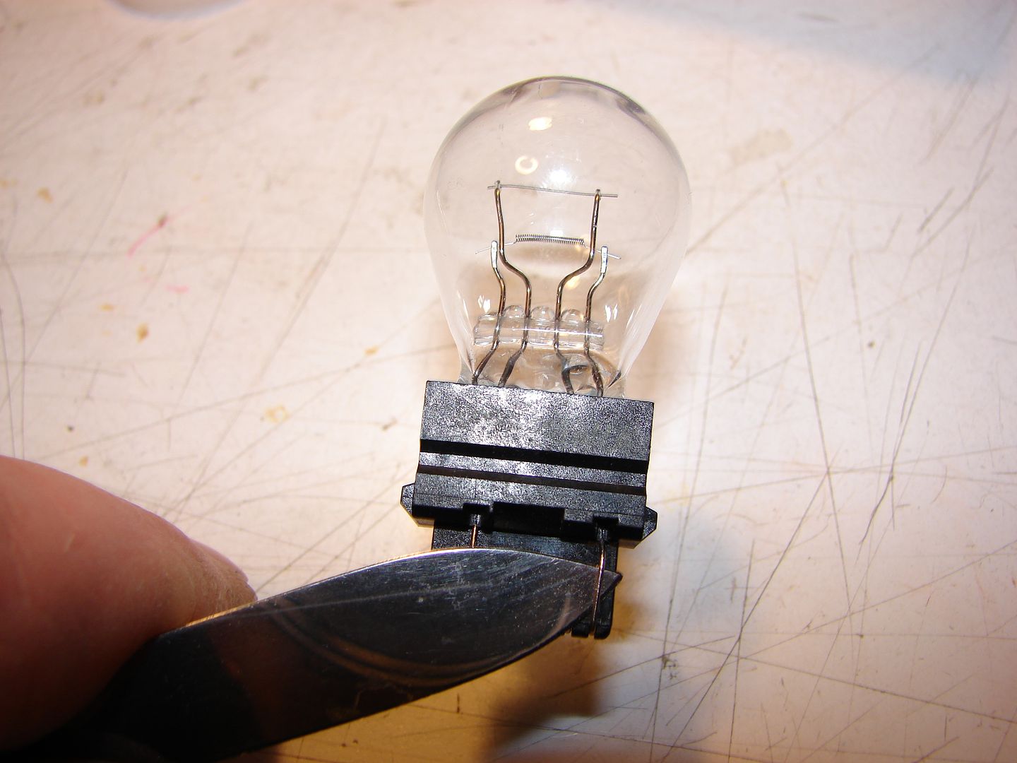
Insert a thin blade under one contact wire (IT DOES NOT MATTER WHICH ONE) and pull it loose from the slot...
| This image has been resized. Click this bar to view the full image. The original image is sized 1024x768 and weights 57KB. |
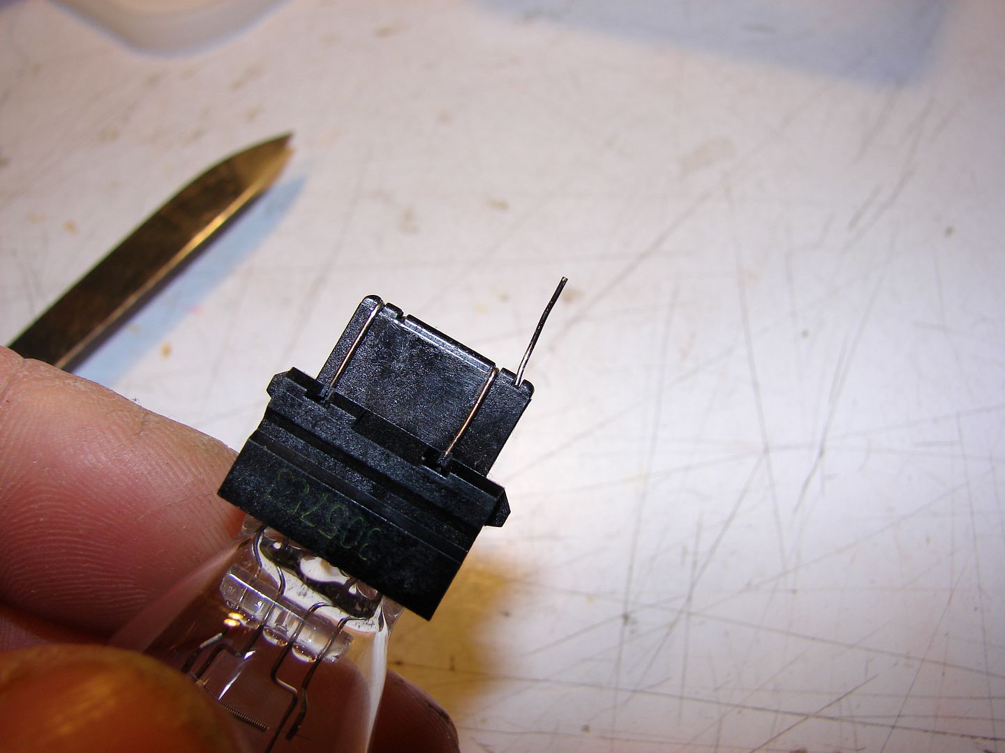
...and straight out away from the wedge base.
| This image has been resized. Click this bar to view the full image. The original image is sized 1024x768 and weights 78KB. |
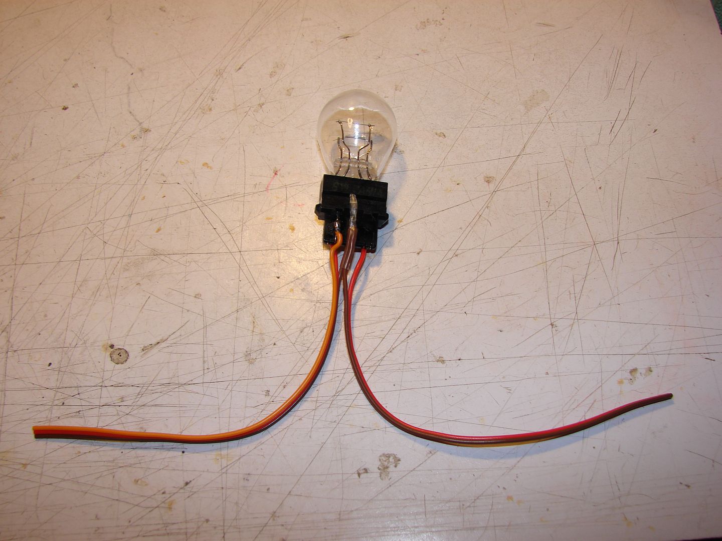
Now wrap it back across the wedge base to the other side, so you have two contact wires right side by side. These two will be your common (B+); solder one red wire to both of them at the same time.
| This image has been resized. Click this bar to view the full image. The original image is sized 1024x768 and weights 85KB. |
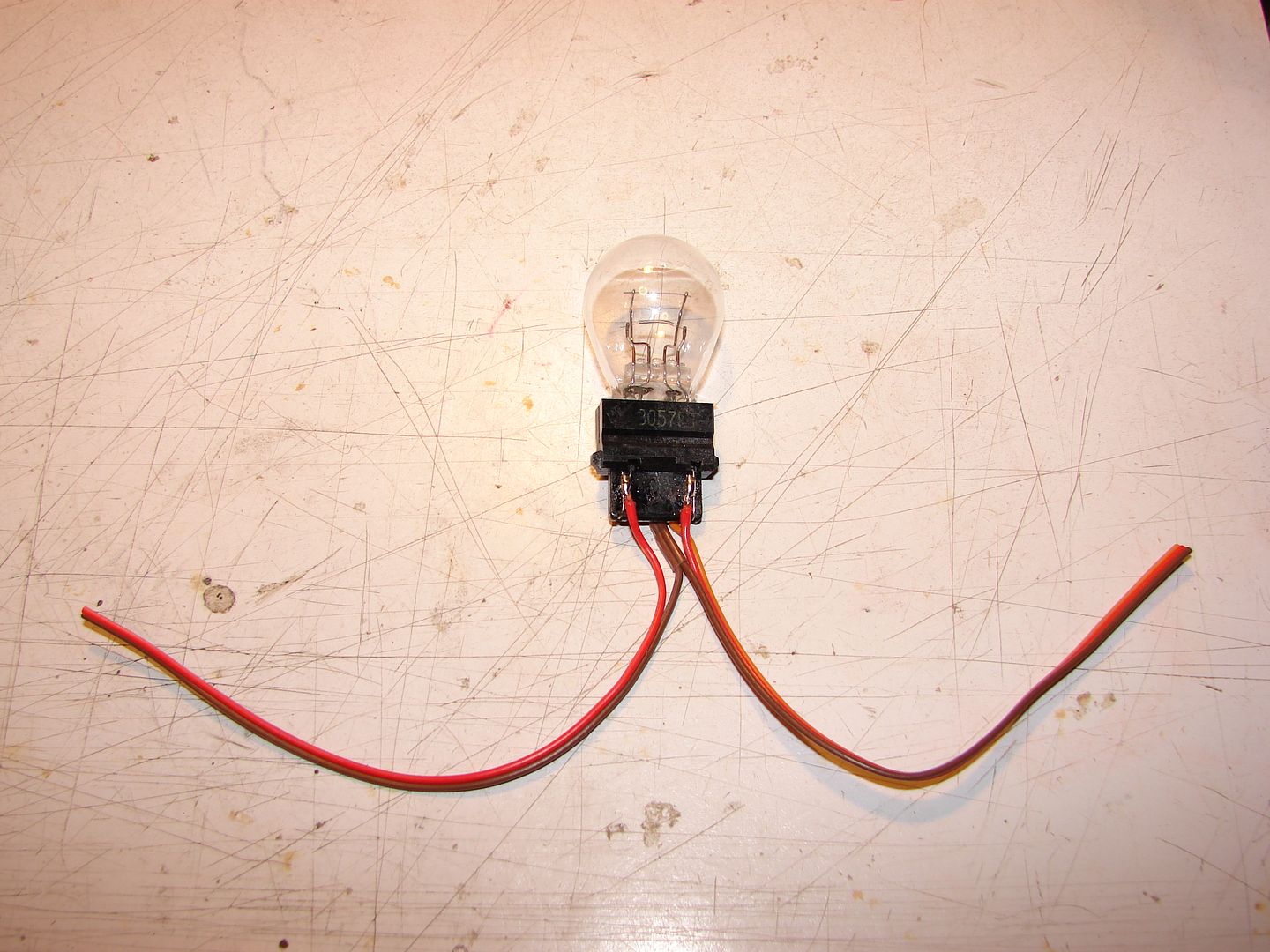
Now you have two contact wires on the other side of the wedge base; the one closest to the outside edge will be your higher current one. Solder your second Red wire to that one. The remaining contact wire is the lower current one, solder a Yellow wire to that.
Here you can see that my 2nd red wire is on the same side of the wedge base as my Common (B+); this is NOT important. If you pick a different wire to bend over the Wedge Base, it might not be on the same side. What is important is that you look for the contact wire that is CLOSEST to the outside edge of the wedge base to be your higher current contact wire.
If you're still not sure, connect your common (B+) to the (+) of a 2S or 3S battery and touch a jumper from the battery (-) to each of the other two contact wires; the one that is brightest will be your high-current filament and gets the 2nd Red wire. The dimmer one gets the Yellow wire.
| This image has been resized. Click this bar to view the full image. The original image is sized 1024x768 and weights 80KB. |
I used a couple scraps of Heavy-Duty Servo Wire (Anything 20-24ga will be plenty) I had laying around to make my Current Limiter; as a result, I needed a place to put the BROWN (GND) wires where I soldered them together. That's why it's shown as part of the schematic; you don't NEED it, you can just use a short Alligator wire for the (GND).
| This image has been resized. Click this bar to view the full image. The original image is sized 1024x768 and weights 51KB. |
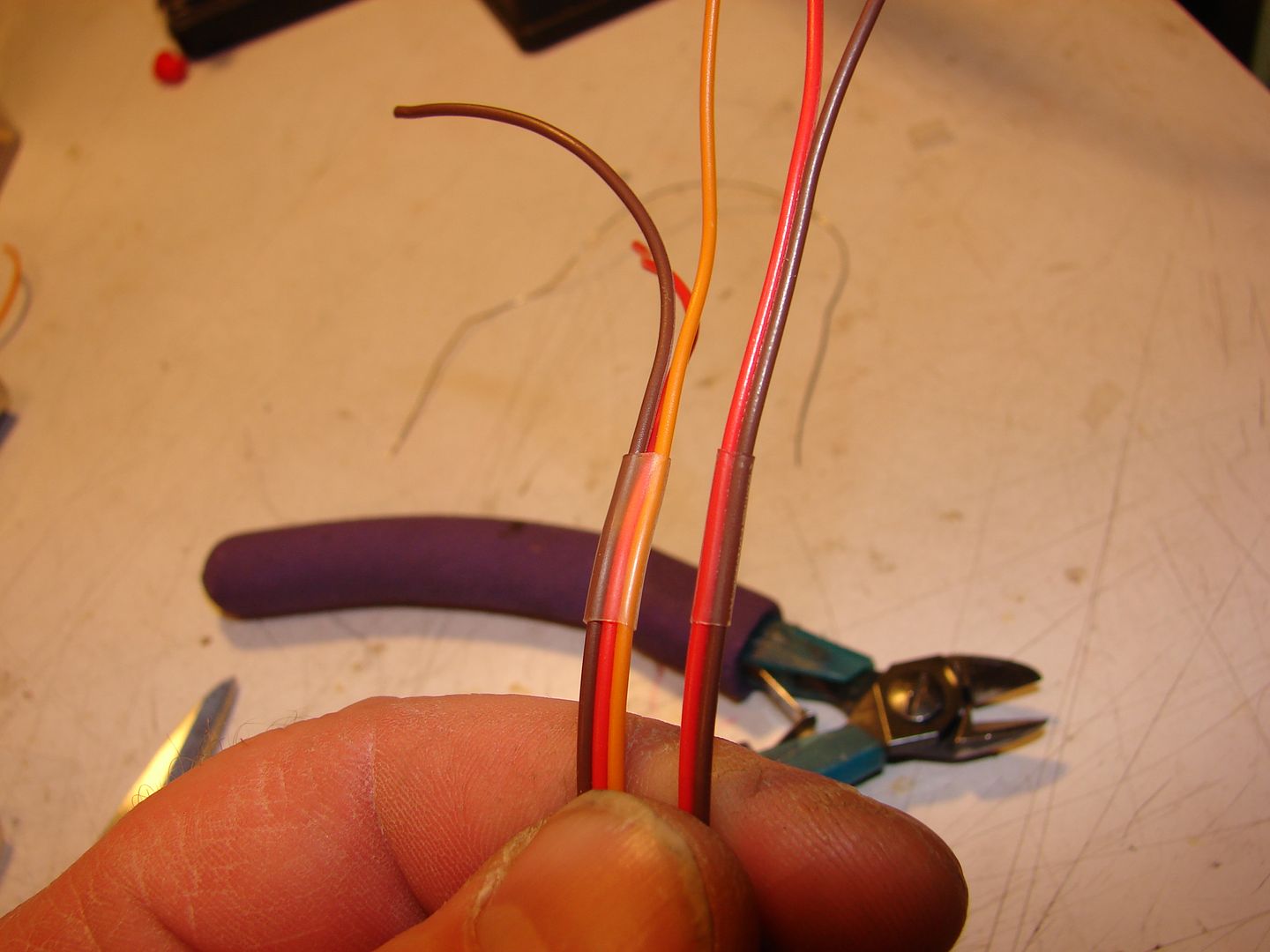
The Alligator clips I used are Radio Shack # 270-378; they cost $3.49. You NEED clips with full shroud like them to keep from burning stuffs up. Alternately, you could cut up a few pre-made alligator wires, but using old servo wires is nice because it helps you not get your (IN) and (OUT) wires mixed up. A little heat shrink like so will keep them from unraveling.
If you're ONLY going to use your Current-Limiter for programming/testing ESCs on the quad, you may want to use a battery connector on the BATT (+) & BATT (-) side for the sake of convenience; this will also eliminate one more chance of hooking power up backwards. I will probably build another one of these myself made just that way for this reason.
For the most part, when you are using this device it should NEVER illuminate; it should ONLY illuminate in cases of short circuit (in which case it just saved you a toasted ESC - Congratulations!) or when testing if you present a fairly high load like spiking the throttle or using too large an ESC/Motor combination.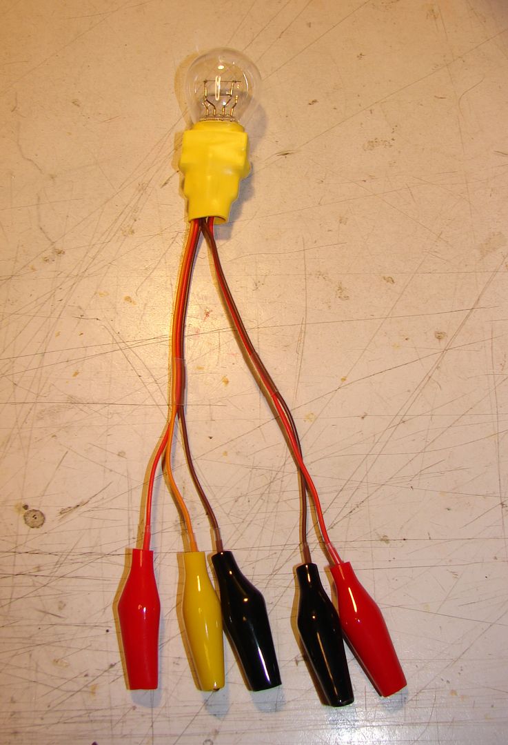
| This image has been resized. Click this bar to view the full image. The original image is sized 1024x768 and weights 67KB. |
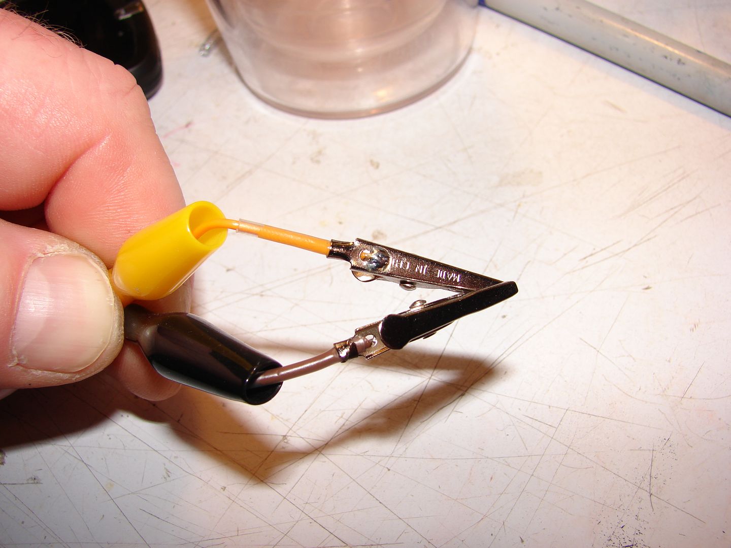
If you look closely you'll see I used short lengths of 2mm ID heat-shrink as stress-reliefs on my wires; please note that you should DEFINTELY solder the wires to the alligator clips, don't just crimp them. This is a mission-critical bit of equipment when it's being used. I'm sorry I didn't take photos of this part of the assembly process, but you should be able to figure it out from this close-up of the insides of the finished connections.
BUILDING A PULL-UP CIRCUIT ADAPTER FROM A SALVAGED SERVO CABLE
| This image has been resized. Click this bar to view the full image. The original image is sized 1024x459 and weights 30KB. |
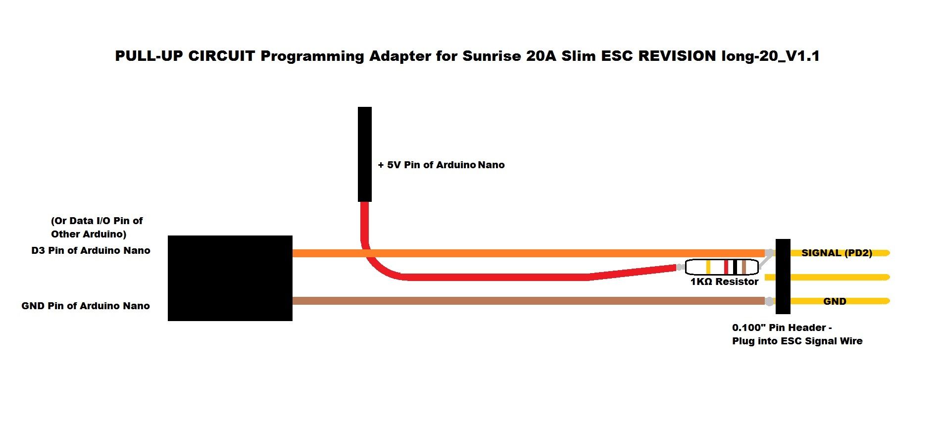
As I mentioned before; this ESC has a pull-down resistor in the input, so it doesn't talk to our 1-Wire Programmers like it should. Here's what happens:
The 20KΩ resistor across Signal IN and GND pulls PD2 LO (See the photo at the top of this How-To). The output from the Arduino switches by pulling the circuit LO as well. Therefore, you need to apply +5V through a resistor to pull the circuit HI by default; this resistor needs to be lower value than the 20KΩ Pull-Down Resistor to do so. With this circuit betwen your 1-Wire programmer and ther ESC, when the output of the Arduino switches LO, there's something for it to modulate.
I had a 1KΩ resistor just laying on my bench and it presents only 5ma load at 5V, so I used it. Achim says that a 2.7KΩ will work fine and not load the output of the Arduino as much; he's probably right, though I haven't tested it.
| This image has been resized. Click this bar to view the full image. The original image is sized 1024x758 and weights 64KB. |
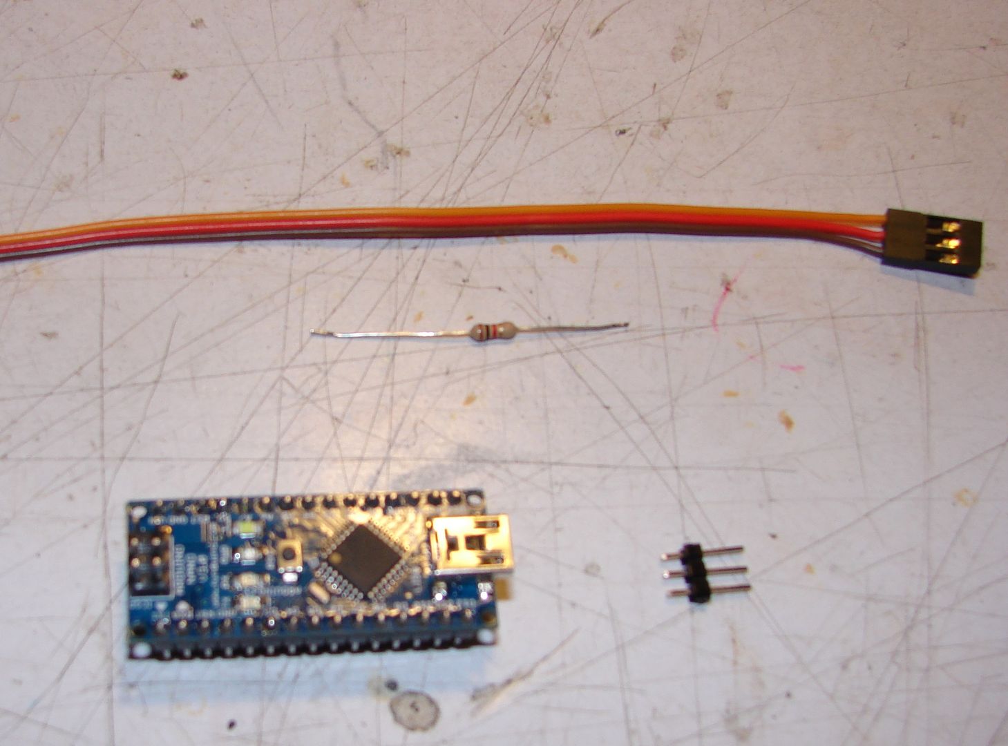
We're going to start with this. The blurry module at the bottom is an Arduino Nano; it's the perfect tool for this job. Please note that this segment is aimed at building the adapter to fit an Arduino Nano; you will have to figure out where things go if you're using a different model Arduino. I have documented as well as I can to make that figuring as easy as possible, though. 
| This image has been resized. Click this bar to view the full image. The original image is sized 1024x768 and weights 59KB. |
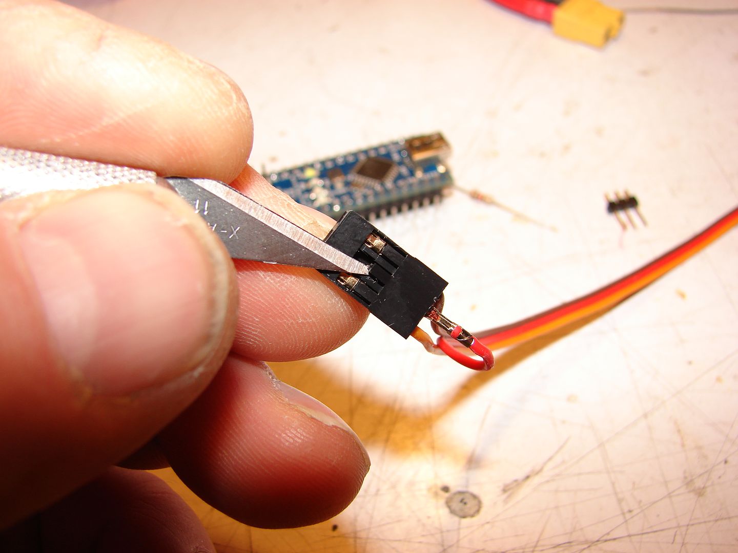
Start by releasing the RED connector from the Servo Plug with the tip if your X-Acto knife; pull it out and unravel it enough to have at least a 4" pigtail.
| This image has been resized. Click this bar to view the full image. The original image is sized 1024x768 and weights 104KB. |
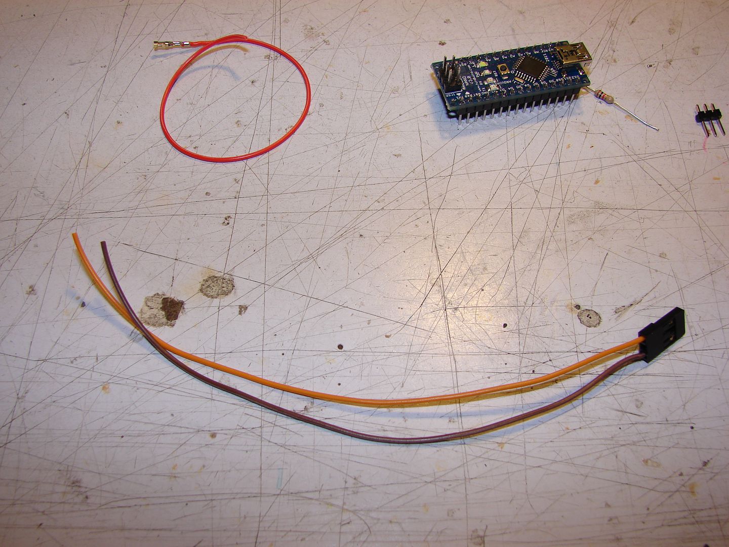
My salvaged servo wire was only 6" long, so I just unraveled the entire length of the red wire.
| This image has been resized. Click this bar to view the full image. The original image is sized 1024x768 and weights 69KB. |
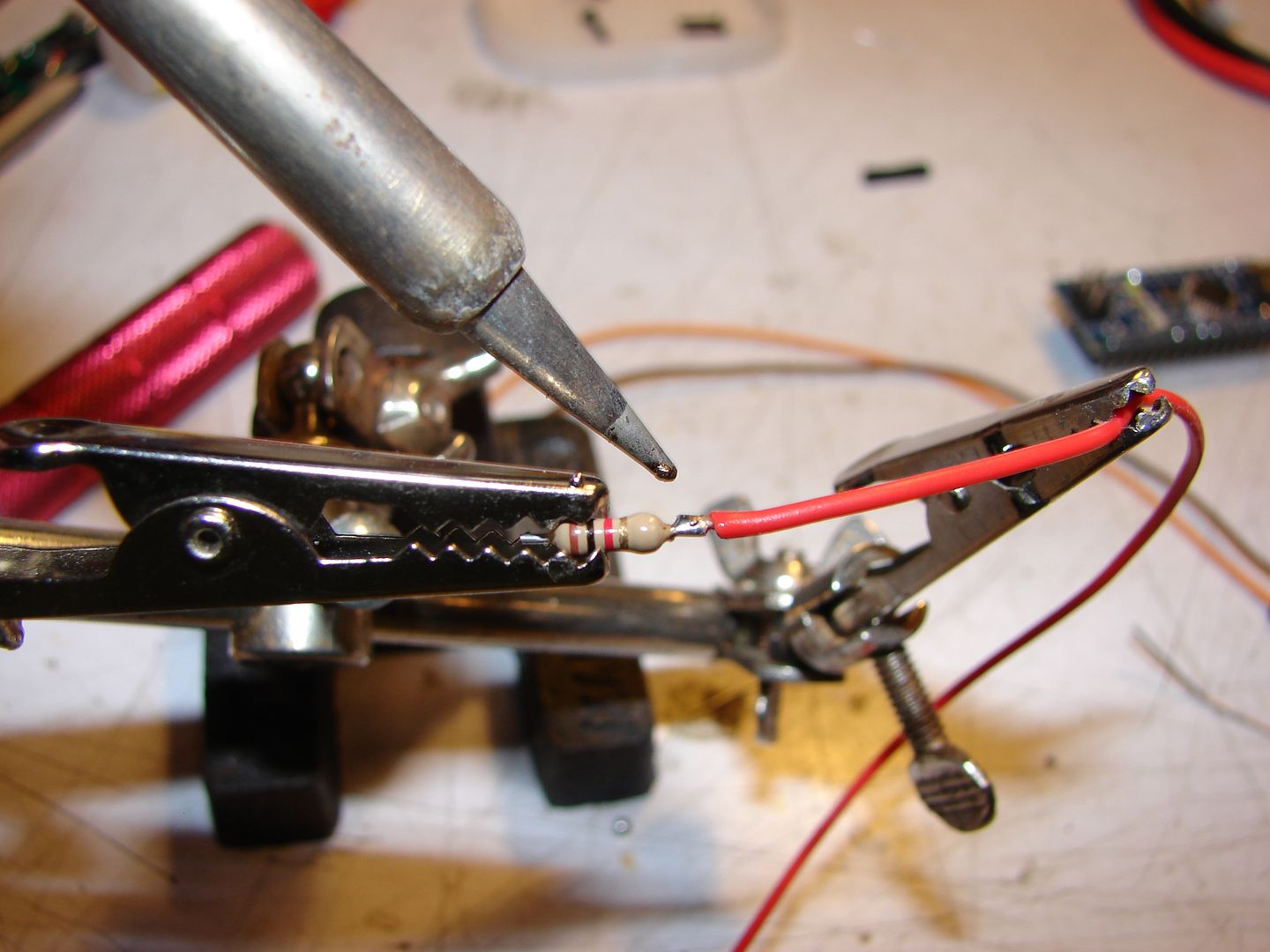
Cut the leads of the 1K resistor to approx 3-4mm long, then solder the not-connector end of the Red wire to one end.
| This image has been resized. Click this bar to view the full image. The original image is sized 1024x768 and weights 69KB. |
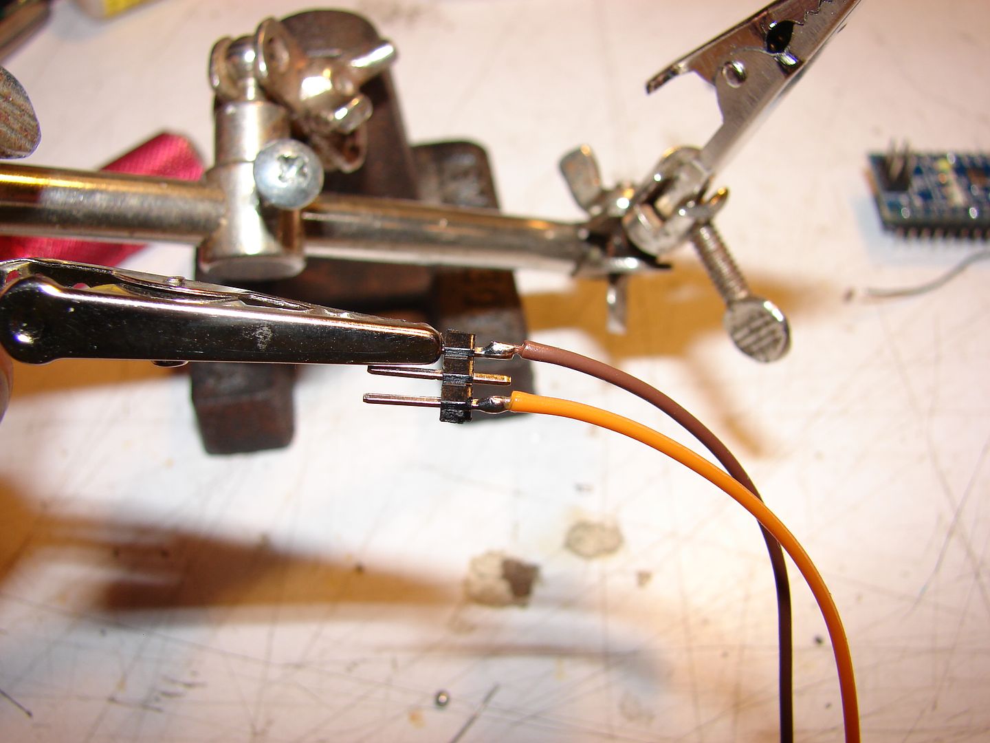
Next, solder the (GND) and (SIGNAL) wires to the outer pins of a 3-pin length of 0.100" header.
| This image has been resized. Click this bar to view the full image. The original image is sized 1024x768 and weights 60KB. |
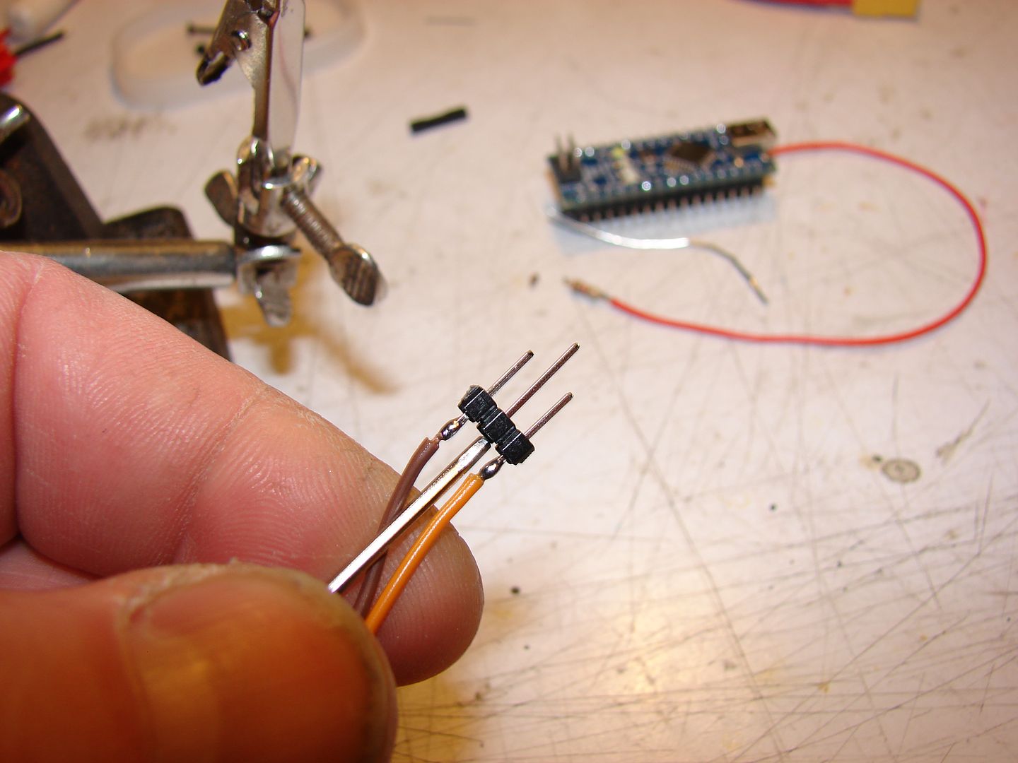
We don't need the center pin, and it's kindof in the way. Just push it out with a screwdriver.
| This image has been resized. Click this bar to view the full image. The original image is sized 1024x768 and weights 62KB. |
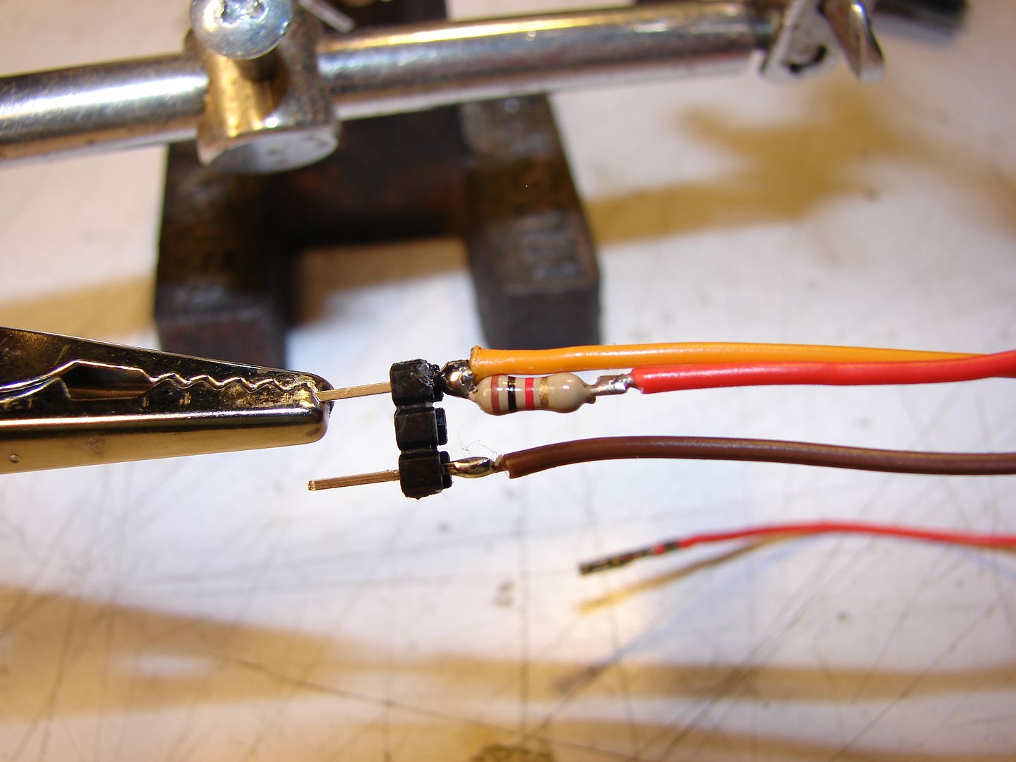
And now, solder the Not-Red-Wire end of the resistor to the same pin as the (Signal) wire.
| This image has been resized. Click this bar to view the full image. The original image is sized 1024x768 and weights 47KB. |
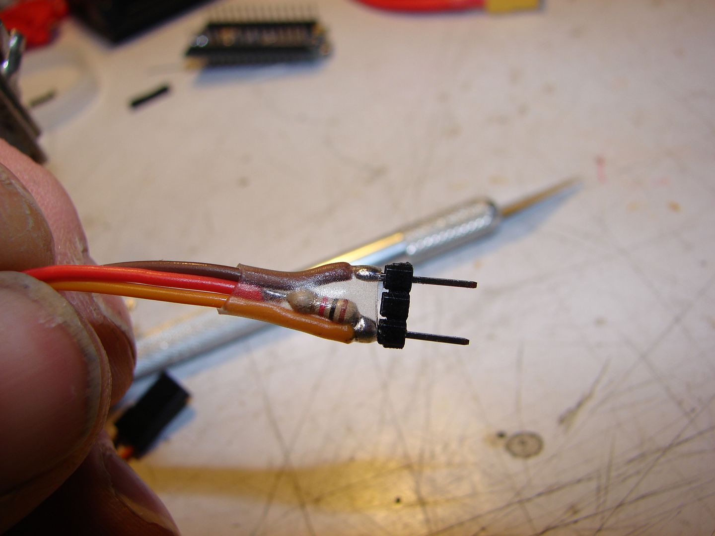
A little heat-shrink for safety's sake... beautiful.
| This image has been resized. Click this bar to view the full image. The original image is sized 1024x768 and weights 46KB. |
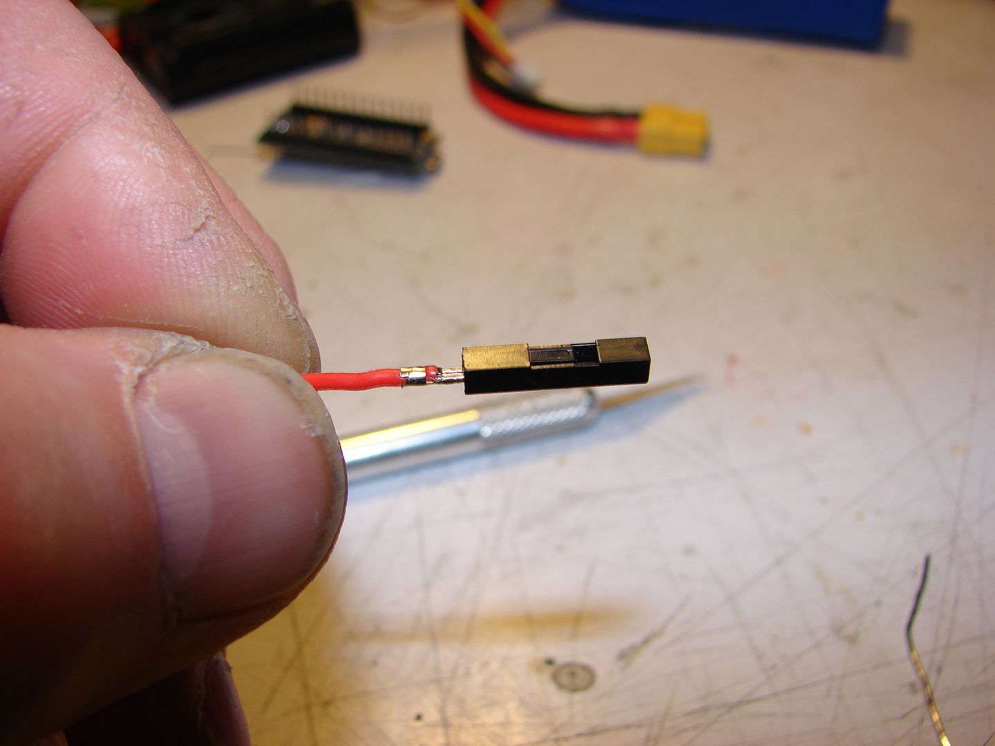
I have oodles of 1-pin 0.100" jumper wire from my Arduino Box; I robbed a shroud from one of those for my 5V comnnector. If you don't, a little 2-3mm ID heat-shrink will work great.
| This image has been resized. Click this bar to view the full image. The original image is sized 1024x768 and weights 88KB. |
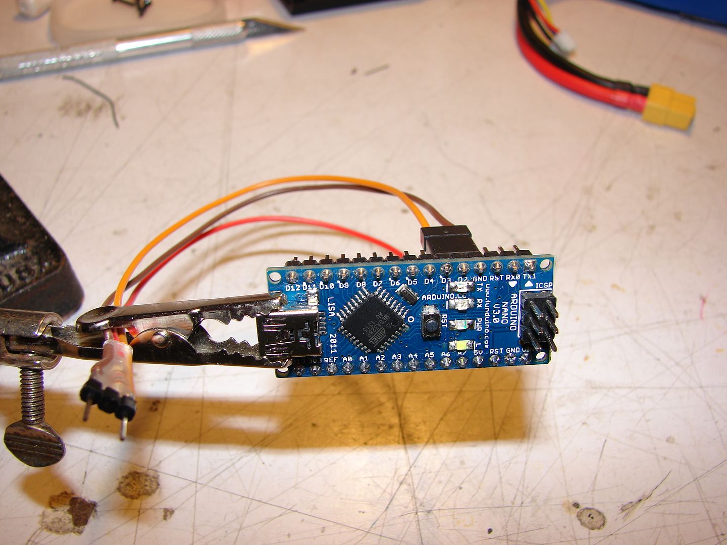
Here's my Arduino Nano all hooked up; (GND) to a (GND) pin, (SIGNAL) to (D3) and the (+5V) to the (+5V) pin on the lower row of headers.
On an Arduino Uno, you'll need to use pins instead of a servo plug, and you'll have to break them all out separately because you don't have 2 wires located conveniently close to each other. (GND) wire and (+5V) go to their respective pins on the Uno; (Signal) wire goes to pin 11 (MOSI).
| This image has been resized. Click this bar to view the full image. The original image is sized 1024x768 and weights 94KB. |
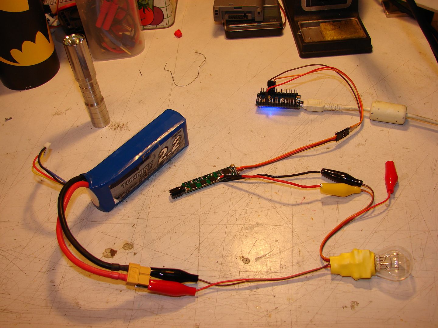
And here it is all hooked up, ready to program an ESC!
But... before we can do that, we have to program our Arduino as a 1-Wire Serial device... fortunately, BLHeliSuite will do THAT for us too!
 model17.ini
